 By guest blogger & Wi-Fi veteran, Steve Hratko, Airvine

We hear a lot about ‘beamforming’ in the trade press, on podcasts, and elsewhere – but what exactly is it and why do we care? Our technology guest blogger this week is Steve Hratko, a Wi-Fi industry veteran and radio network expert at award winning startup, Airvine. Getting beamforming right is one reason why Airvine’s all-wireless enterprise technology in 60 GHz is capable of blasting radio signals through walls.
Beamforming – what is it?
Beamforming involves the precise phase shifting of the elements of an antenna array to generate a very narrow beam focused in a very specific direction. The narrow beam greatly increases the gain as seen by the intended receiver, while at the same time reducing interference as seen by other devices in close proximity. It is useful in sub-6 GHz applications, but its real value comes in the mmWave bands where it helps to overcome the very high free space path loss[1] (FSPL) and oxygen absorption[2] that occurs at 60 GHz. Beamforming can be done in three different ways:
- Analog beamforming
- Digital beamforming
- Hybrid beamforming
A high-level overview of these different techniques will lead to a discussion of MIMO (multiple input, multiple output) technology, which is a form of spatial multiplexing that leverages beamforming technology. There are two parts to any radio system; and they are the digital baseband (aka modem) and the RF subsystem (radio chain + antenna array). Each has a role to play in the beamforming process.
Analog Beamforming
With analog beamforming a single data stream is sent from the digital baseband through a radio chain that creates an analog signal in the mmWave band. That signal is then sent through an array of phase shifters to create a very narrow beam with a tremendous amount of gain. Depending on design you could see as much as a 30 dBi[3] (decibel relative to isotropic) of antenna gain from a large array. These arrays use patch antenna elements, which are each about 2 millimeters square when operating at 60 GHz.
Enjoying this story?
Leave your email here and we'll get you all the latest Wi-Fi news.
It is possible to have as many as 256 patch antenna elements in an array and each is fed by a unique phase shifter that is under the control of the digital baseband. By precisely altering the phase (and amplitude) of each of the 256 patch antenna elements, it is possible to create a very narrow beam focused in a very specific direction. Since power as defined by EIRP (Effective Isotropic Radiated Power) is limited by regulation[4], the narrower the beam, the greater the gain as seen by the intended receiver.
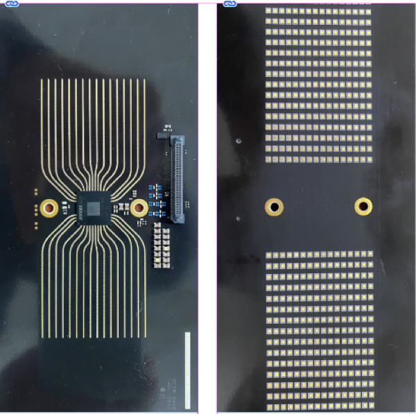
The photo to the left shows the antenna board for the Airvine WaveTunnel node. It consists of 256 patch antenna elements (16 x16) on the receive side and another 256 patch elements on the transmit side. Airvine uses analog beamforming to create a very high-gain antenna in its ground-breaking WaveTunnel technology.
Digital Beamforming
In this approach all phase shifting is done in the digital baseband. This enables incredibly precise beams and nulls (absence of RF energy), but it doesn’t scale well as you need a full radio chain for each antenna element. A typical implementation might include 16 data streams flowing through 16 radio chains, and from there into 16 antenna elements.
One nice feature of digital beamforming is that it can support multi-user MIMO, which makes it possible to communicate with multiple users over the same RF channel at the same time. To limit interference, MU-MIMO requires a very narrow beam focused at each intended user, with nulls focused at everyone else. This brings us back to beamforming which is best done in the mmWave bands with a large number of antenna elements (ideally several hundred). Such an implementation in the digital domain is cost and power prohibitive. A compelling alternative would be to combine the large arrays possible with analog beamforming with the MU-MIMO capabilities of digital beamforming. Enter hybrid beamforming.
Hybrid Beamforming
This approach is getting a lot of attention in both the 5G and Wi-Fi worlds. Multiple data streams (up to 8 and eventually 16) come out of the digital baseband and flow through multiple independent radio chains (one for each data stream) that produces analog signals in the mmWave band. These are then phase shifted in the analog domain and sent out through an array of patch antenna elements. All phase shifting calculations are handled by the digital baseband and sent on to the antenna arrays.
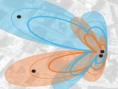
By the careful formation of beams and nulls it is possible to talk to multiple users simultaneously over the same RF channel at the same time without any undue interference. The use of phase shifting in the analog domain allows this approach to scale far beyond what could be done with digital beamforming. The figure on the left shows how these different beams can be focused at different users in the service area. The narrower the beam the higher the gain and the better the service, but a narrow beam requires a large number of antenna elements.
This combination of multi-user MIMO and analog beamforming is often referred to as MASSIVE MIMO. Each beam is structured to deliver maximum energy to the intended user, while at the same time generating nulls aimed at all other users. As users move around in the coverage area the digital baseband recalculates all the phase shifts to keep everyone happy. The beauty of operating in the V-band (60 GHz) is that an array of 256 path antenna elements can easily fit on a PCB of less than 30 square centimeters.
To do the same in the Wi-Fi bands down at 5 GHz would require a much larger antenna module. This approach is ideal for access networks (Wi-Fi or 5G) that are being deployed in heavily congested areas like stadiums, city centers, convention centers, and airports where it is necessary to connect huge numbers of people in a fairly confined area.
Receive Beamforming
Most discussions of beamforming focus on the transmit side of the equation, but there is also a receive side that must be considered. Not only is the RF signal phase shifted across all 256 transmit patch antenna elements, but it must also be phase shifted across the receive side as well.
The purpose of this step is to get all 256 receive signals aligned and in phase so that they can be added together to get a strong signal. This is most easily explained by considering an example where the transmitter is to the left of the receiver. This means all the patch antenna elements on the left side of the receiver’s PCB will see the signal before the patch elements on the right side. These signals can’t be successfully added together until they are all in-phase.
Side Lobes
The creation of side lobes of radio energy is an inevitable part of the beamforming process. There will always be some extraneous RF energy that is not part of the primary beam. The goal is to minimize this energy to the extent possible. These lobes will look like interference to other users in the operating area, and they take energy away from the primary beam that is directed at the intended user. A general objective in any mmWave project is to target side lobe suppression of at least 20 dB. This means that side lobe traffic is at least 100 times weaker than the primary beam.
Conclusions
Beamforming technology is ideally suited for the mmWave bands as it can fit into a very small enclosure, easily overcomes free space path loss, and limits co-channel interference. There are three major beamforming approaches that can be used, with the analog implementations being best suited to backbone applications in the V-band because of its ability to build large arrays that create narrow beams at very high gain. All of which is perfect for punching through walls @ 60 GHz.
For more on beamforming in the V-band visit www.airvine.com
![]()
References:
[1] Free Space Path Loss (FSPL) as defined by FRIIS = 32.4 + 20log10(d) + 20log10(f) where d is in kilometers and f is in MHz
[2] Oxygen absorption can reach 15 dB per kilometer at 60 GHz which adds to the range limitations of the V-band. This number tends to get dwarfed by FSPL which can hit 100 dB at 100 meters.
[3] dBi measures antenna gain in a specific direction relative to an isotropic antenna which is a hypothetical antenna that radiates equally in all directions. A gain of 30 dBi means that a beam formed signal can be 1000 times stronger (as seen by the receiver) than one that radiates equally in all directions. One thousand times stronger!