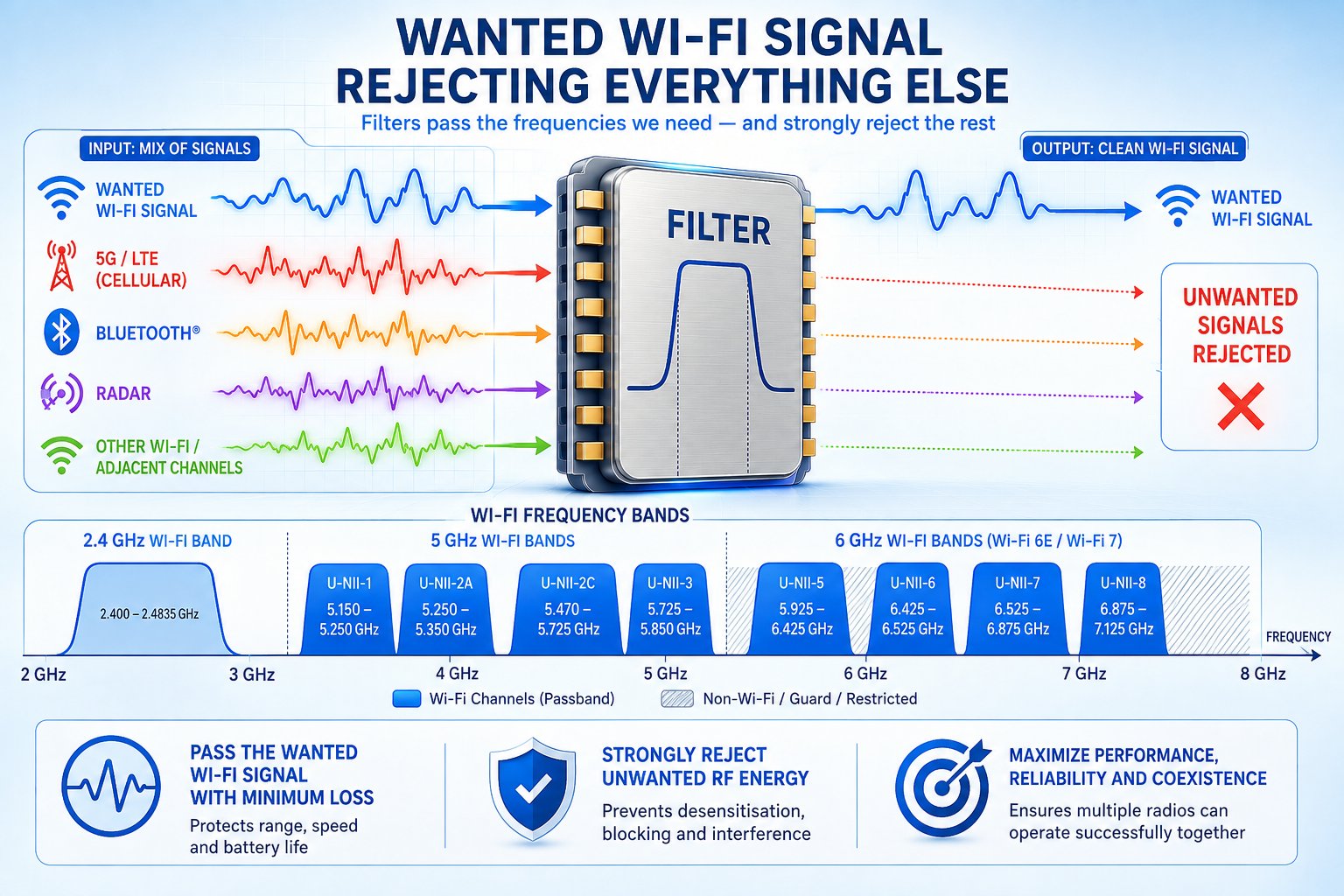

Wi-Fi radios have a deceptively simple job: Transmit and receive radio signals within the frequencies allocated to Wi-Fi. In practice, however, the RF environment surrounding a Wi-Fi radio is crowded with signals that the receiver does not want – and some of the strongest unwanted signals may originate from radios inside the same device. This is where RF filters become essential.
A filter allows wanted frequencies to pass through the RF signal chain while attenuating frequencies outside the required band. That basic description has been true for decades. What has changed is the difficulty of the task because Wi-Fi now operates across the 2.4 GHz, 5 GHz, and 6 GHz bands. Devices increasingly support multiple Wi-Fi bands simultaneously, use wider channels, incorporate multiple spatial streams, and coexist with Bluetooth, cellular, GNSS, and other radios. At the same time, RF components are expected to occupy less space, introduce very little signal loss, and operate power efficiently. The result is that filtering has become one of the critical engineering disciplines behind high-performance Wi-Fi.
What does a Wi-Fi filter actually do?
An ideal filter would be simple: It would pass every wanted Wi-Fi signal without changing it and completely eliminate everything outside the required frequency range. Real filters cannot do this. Every practical filter introduces some loss to the wanted signal. And instead of transitioning instantaneously between frequencies that pass and frequencies that are rejected, the response changes over a finite frequency range. Several characteristics therefore matter when evaluating a filter:
- Passband: The range of frequencies the filter is designed to pass.
- Insertion loss: The signal power lost as the wanted signal passes through the filter.
- Rejection: How strongly signals in unwanted frequency ranges are attenuated.
- Transition band: The frequency interval over which the filter changes from passing signals to rejecting them.
- Isolation: The degree to which signals or RF paths are prevented from interfering with one another.
For Wi-Fi system designers, these characteristics represent a series of compromises. Low insertion loss is highly desirable because every fraction of a decibel lost in the RF path affects the link budget. On transmit, losses between the power amplifier and antenna mean that more PA output may be required to achieve a given radiated power. On receive, losses ahead of the low-noise amplifier can degrade receiver sensitivity.
But high rejection is also essential. Without sufficient attenuation of unwanted signals, energy from another transmitter can reach sensitive parts of the Wi-Fi receiver and impair its ability to detect comparatively weak Wi-Fi signals. The filter designer therefore faces a fundamental challenge: Reject as much unwanted energy as necessary while losing as little of the wanted Wi-Fi signal as possible.
Three Wi-Fi bands create different filtering problems
The expansion of Wi-Fi spectrum has substantially increased the complexity of the RF front end. The 2.4 GHz band presents a particularly challenging coexistence environment. Wi-Fi shares this spectrum with Bluetooth and other technologies, and devices such as smartphones, PCs, access points, gateways, and IoT products may contain multiple radios operating in or around the same frequencies.
The 5 GHz band provides considerably more spectrum, but Wi-Fi operation is distributed across multiple frequency ranges subject to regulatory requirements that vary by geography. The introduction of 6 GHz Wi-Fi with Wi-Fi 6E – and its expanded use with Wi-Fi 7 – created another major RF filtering challenge. The 6 GHz allocation provides a large amount of contiguous spectrum, enabling wide Wi-Fi channels including 160 MHz and, with Wi-Fi 7, 320 MHz channels where regulations and available spectrum permit.
Passing such wide signals efficiently while maintaining sufficient rejection outside the required band places demanding requirements on RF filtering. The challenge also varies geographically. The spectrum authorised for unlicensed 6 GHz operation is not identical in every country. A filter solution suitable for one regulatory market therefore cannot automatically be assumed to be optimal for another.
More Wi-Fi spectrum is enormously valuable – but from an RF design perspective, more spectrum does not necessarily make the job easier.
Coexistence: The interferer may be inside the device
One of the most important reasons for RF filtering is coexistence. It is tempting to imagine interference primarily as signals arriving from neighbouring access points, mobile networks, or other devices in the surrounding environment. Those signals certainly matter, but some of the most difficult RF coexistence problems can occur inside the product itself.
Consider a smartphone, laptop, or cellular gateway containing Wi-Fi, Bluetooth, and cellular radios. One radio may be transmitting at relatively high power while another is attempting to receive a much weaker signal. The antennas and RF circuits involved may be separated by only a small physical distance.
A strong unwanted signal does not necessarily need to fall directly inside the Wi-Fi channel to cause problems. Sufficiently strong energy outside the desired receive band can affect receiver performance. Transmitter leakage, receiver blocking, adjacent-band interference, and other RF effects can reduce the receiver’s ability to recover the wanted signal. The practical consequence can be receiver desensitisation: The Wi-Fi receiver becomes less capable of detecting weak Wi-Fi signals because of the presence of a much stronger unwanted signal. Filters provide part of the defence.
By attenuating unwanted frequencies before they reach sensitive receiver circuitry—and by suppressing unwanted emissions and frequency components in transmit paths—filters help create the RF isolation required for multiple radios to operate successfully within the same product. This makes coexistence a system problem rather than simply a Wi-Fi problem.
Why is Wi-Fi filtering becoming harder?
Several trends are occurring simultaneously. Wi-Fi channels have become wider. Wi-Fi devices support more frequency bands. Multi-band and multi-link operation are becoming increasingly important. Products incorporate more radios. Device designers continue to demand smaller RF implementations. And Wi-Fi performance expectations continue to increase. These requirements frequently work against one another.
A filter needs a sufficiently wide passband to accommodate the wanted signal while still providing strong rejection where it is required. In some cases the frequency separation between what needs to pass and what needs to be strongly attenuated can be relatively small.
The transition between passband and stopband therefore matters enormously. Engineers sometimes describe the steepness of this transition as the filter’s skirt. A steep filter response can help separate closely spaced wanted and unwanted frequencies. But achieving the required combination of steep rejection, low insertion loss, power handling, size, temperature stability, and cost is not trivial. There is another important system-level consequence: Insertion loss and power efficiency are connected.
Loss in the transmit path means some RF power produced by the PA never reaches the antenna. Compensating for that loss can require additional PA output, which in turn can increase electrical power consumption and heat generation. In compact multi-radio products, fractions of a decibel can therefore have consequences beyond the RF link budget. Filters are passive components, but their performance can influence the power and thermal design of the complete device.
SAW, BAW, and other approaches to RF filtering
Many RF filters used in wireless devices employ acoustic resonator technologies. Two terms frequently encountered are SAW, or surface acoustic wave, and BAW, or bulk acoustic wave. In simplified terms, these technologies convert electrical RF energy into mechanical acoustic energy within a piezoelectric structure, use resonant behaviour to create the required frequency-selective response, and convert the signal back into electrical energy.
SAW technologies have been widely used for RF filtering and can provide compact, cost-effective solutions for many frequency ranges and applications. BAW technologies use acoustic waves propagating through the thickness of the resonating structure rather than primarily along its surface. BAW implementations can offer advantages for demanding filtering requirements at higher frequencies and where steep rejection, bandwidth, or power handling requirements become challenging.
The real technology landscape is more nuanced than a simple choice between SAW and BAW. Different acoustic-filter architectures, materials, resonator structures, and manufacturing techniques allow suppliers to optimise performance for particular frequency bands and applications. For the Wi-Fi system designer, the relevant question is therefore not simply Which filter technology is best?
Instead the question is: Which filtering solution delivers the required passband, rejection, insertion loss, size, power handling, temperature behaviour, and cost for this particular RF design? The answer may be different for 2.4 GHz, 5 GHz, and 6 GHz—and different again depending on what other radios must coexist in the product.
The filter cannot be designed in isolation
A filter specification on a component data sheet tells only part of the story. The filter operates as part of an RF chain that may include a power amplifier, low-noise amplifier, switches, matching networks, PCB transmission lines, connectors, and antennas. Its behaviour also interacts with the physical layout of the product and with other nearby RF systems.
This is why FEM integration has become so important. Integrating filters with other RF front-end functions can reduce external component count and simplify parts of the RF implementation. It can also allow suppliers to optimise the interaction between PA, LNA, switching, matching, and filtering functions as a combined RF subsystem. But integration does not eliminate the underlying RF trade-offs.
Ultimately, Wi-Fi performance depends on what happens across the complete signal path—from the radio through the front end and antenna and into the surrounding RF environment. A filter with excellent rejection but excessive insertion loss is not necessarily a good solution. Neither is a low-loss filter that fails to provide sufficient protection against the interference environment the device will encounter. The objective is not to build the theoretically strongest filter. It is to build the right filter as part of the right RF system.
WiFi NOW’s take: Wi-Fi’s expansion into 6 GHz has delivered one of the largest increases in usable spectrum in the technology’s history. But exploiting that spectrum efficiently requires increasingly sophisticated RF engineering. Filters are easy to overlook because they do not create new Wi-Fi features, increase modulation rates, or add spatial streams. Yet they determine how much of the wanted RF signal survives the front end—and how effectively unwanted energy is kept out.
As Wi-Fi devices become more multi-band and multi-radio, we expect filtering and RF coexistence to become increasingly important differentiators in real-world product performance. More spectrum gives Wi-Fi more capacity. Better RF filtering helps make that spectrum usable.
/Claus.